Introduction
Universal rolling mills produce heavy rails and various section steel. During rail rolling, axial shift of roll chocks creates big troubles for dimensional accuracy. In fact, the rational design and regular maintenance of retainer plates directly stop roll chock axial movement.
This paper targets frequent retainer plate breakdowns in recent production. First, it introduces retainer plate structure and core functions. Next, it explains the full hydraulic control logic for retainer plates. Then it analyzes root causes of typical faults one by one. After that, the article proposes targeted upgrading plans. All improvement measures have been put into real production and deliver stable obvious effects.
Keywords: universal rolling mill, retainer plate, mechanical fault, hydraulic control system, rolling mill maintenance
1 Structure & Working Functions of Retainer Plates
A universal rolling mill contains horizontal rolls and vertical rolls. Horizontal rolls shape the web of steel workpieces and install on upper and lower roll chocks. Vertical rolls form top and bottom edges of materials and fix inside vertical roll housings.
Rail production sets strict standards for pass dimensional precision. For this reason, stable locking of roll chocks becomes extremely important. If roll chocks shift axially, finished rail sizes go out of tolerance, and normal rolling will be interrupted.
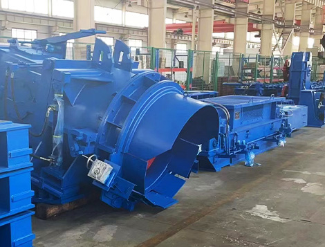
Four hydraulic-driven retainer plates mount on the operation side of the mill housing. Two plates sit at the mill entry, and the other two sit at the exit. Each plate works on upper and lower roll chocks separately.
First, retainer plates lock roll chocks tightly during rolling. They fully block axial displacement caused by rolling impact. Second, they assist the roll change process. When replacing rolls, the mill housing splits into two parts. The drive-side housing stays fixed, while the operation-side housing moves outward.
At this stage, retainer plates keep locked. They pull the whole roll set together with the operation-side housing to the roll change platform. After reaching the designated position, retainer plates unlock. The operation-side housing separates from roll assemblies to finish roll replacement smoothly.
2 Hydraulic Control System of Retainer Plates
The hydraulic circuit controls three working modes of retainer plates: lock, gap adjustment and open. The whole system includes a 3-position 4-way electromagnetic reversing valve, one check valve, one pressure reducing valve, one electromagnetic ball valve, two one-way throttle valves and one overflow valve. The overflow valve sets maximum pressure at 31.5 MPa. Four hydraulic cylinders and matched pipelines complete the whole hydraulic layout.
2.1 Lock Mode
Workers finish roll gap adjustment first. Then the hydraulic valve group starts running. Coil a of the reversing valve gets powered, and the electromagnetic ball valve opens at the same time.
Pressurized oil flows through port P into chamber a of each cylinder. Oil inside chamber b flows back to the oil tank via port T. The piston rod stretches outward. Once the wedge head of the retainer plate fully locks the roll chock, the electromagnetic ball valve cuts power. It seals oil inside cylinders to maintain stable locking force.
2.2 Roll Gap Adjustment Mode
After one pass of rail rolling, operators need to readjust roll gaps. At this moment, coils a and b of the reversing valve lose power and stay at the neutral position. The electromagnetic ball valve opens to release pressure.
Oil in both cylinder chambers returns to the tank naturally. The piston rod bears no external force. Disc springs installed at the rod tail pull the rod back about 0.5 mm by elastic force. A small gap forms between the wedge head and roll chock. This gap allows free movement of rolls during gap calibration.
2.3 Open Mode for Roll Change
When coil b of the reversing valve receives power, the electromagnetic ball valve opens. Pressurized oil enters cylinder chamber b and pushes the piston rod inward. Oil inside chamber a flows back through port T.
After the rod retracts fully, all electromagnetic coils cut power. The retainer plate stays open for roll replacement. Besides, two SBE inductive proximity switches mount at the tail of each hydraulic cylinder. They detect real-time piston rod positions and guarantee safe equipment operation.
3 Root Cause Analysis & Fixes for Common Retainer Plate Faults
Rail rolling generates huge impact force on work rolls. Locked retainer plates bear all transferred impact loads. Long-time alternating force creates multiple typical failures. Common faults cover broken cylinder piston rods, stuck unopenable retainer plates, cracked tail cover bolts with oil leakage, incomplete rod retraction and locked blocks jamming roll chocks.
When retainer plates lock roll chocks, zero clearance exists between wedge heads and chocks. We split impact force into two components via trigonometric formulas: F1=Fsinα and F2=Fcosα. Horizontal force balances against bending strength of the cylinder T-head and piston rod. Axial force bears on compressive strength of the piston rod directly.
3.1 Fault 1: Broken Piston Rod Caused by Improper Clearance Setting
3.1.1 Root Cause
Zero clearance stands as the ideal state during locking. However, manual adjustment rarely hits this standard. Extra clearance appears between wedge heads and roll chocks easily.
The instant steel bite brings strong impact. Roll chocks shift and collide with the T-head of retainer cylinders. Large vertical component force creates cyclic fatigue on weak rod sections. Finally, the piston rod cracks completely.
3.1.2 Practical Handling Steps
- Switch retainer plates to open mode, then fully loosen two adjusting nuts at the cylinder tail.
- Feed pressurized oil into port a to extend piston rods. Make sure wedge heads touch roll chocks with zero clearance.
- Tighten the first adjusting nut until it touches disc springs. Rotate the nut another 1/4 turn. The rotation creates a standard 0.2 mm gap calculated by thread pitch and wedge angle. Install lock nuts to prevent loosening.
The 0.2 mm gap lets disc springs pull rods back during gap adjustment. Meanwhile, it eliminates collision impact during steel feeding and stops rod fracture.
3.2 Fault 2: Retainer Plate Stuck and Fails to Open
3.2.1 Root Cause
Continuous impact and vibration during rail rolling loosen thread connections between retainer plates and piston rods. When the hydraulic system sends retraction signals, the rod spins freely without driving wedge heads, leading to stuck locking parts.
The original round T-head rotates relative to wedge blocks. Once threads loosen, maintenance staff cannot rotate rods to reset connections quickly. It takes long downtime to fix the jammed plates.
3.2.2 Improvement Solution
- Replace round T-heads with square T-heads. Square shapes restrict relative rotation between T-heads and wedge blocks.
- Change separated piston rod and piston shaft into an integrated one-piece component. Integrated structure simplifies assembly and allows easy manual rotation of rods to re-engage loose threads on site.
3.3 Fault 3: Cracked Tail Cover Bolts and Hydraulic Oil Leakage
3.3.1 Root Cause
Cylinders work under 10 MPa locking pressure during rail rolling. The pressure transfers directly to six M8 cover bolts with grade 8.8 strength.
Calculation shows single bolt tensile strength reaches 800 MPa, yield strength hits 640 MPa. Transient impact pressure often exceeds 10 MPa during production. Overloaded bolts crack gradually and cause oil leakage, which disrupts continuous rolling.
3.3.2 Handling Measure
Limited installation space on cylinder end caps stops adding more bolts. We upgrade bolt specifications and material grade instead. Replace original M8 grade 8.8 bolts with M10 grade 10.9 bolts. Higher tensile and yield strength largely reduce bolt cracking failures.
4 Upgrading Schemes for Retainer Plate Hydraulic Control Circuits
4.1 Upgrade Pressure Reducing Valve Setting & Installation Position
The original pressure reducing valve set locking pressure at 10 MPa only. This pressure cannot supply enough clamping force. Roll chocks vibrate due to incomplete locking and ruin rolling stability.
We adjust the valve setting pressure to 20 MPa. Meanwhile, move the pressure reducing valve to the oil inlet pipeline before the 3-position 4-way reversing valve. Field test data proves the new layout delivers stable and reliable locking performance.
4.2 Add Accumulators for Vibration Absorption
Impact force on wedge heads creates strong vibration when steel enters the mill. Vibration loosens T-head threads and fixing bolts. Meanwhile, sealed oil inside cylinder chamber a gets compressed rapidly and forms abnormal pressure buildup.
We install hydraulic accumulators on control circuits. Accumulators absorb instantaneous pressure shock and cut system vibration. They effectively stop thread loosening and retainer plate mechanical damage.