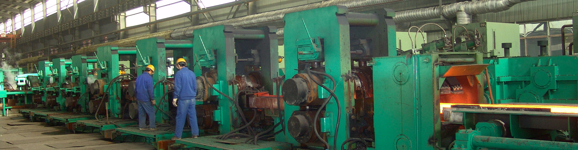
Roll grinding and roll change set the rhythm of a mill roll shop. Between campaigns the shop grinds each roll back to its crown, measures the curve, and records it. On a tonnage trigger the crew pulls the roll out of the stand and pushes a fresh one in. Roll grinding and roll changing both run against the mill’s rolling schedule, so sequence matters as much as tolerance. The sections below cover grinder setup, roll grinding allowance, crown and bearing configuration, change cycles in tonnes, and three change sequences as a medium plate mill runs them.
Grinder Setup Before the Wheel Touches the Roll
Pre-start checks
- Check every button and indicator lamp on the machine. Confirm the grinding wheel mounts securely and shows no wobble. Confirm the tailstock locks, and that the oil and water supply systems work. Only then start the machine.
- Check that the soft-landing pad height suits the roll. The pad must touch the roll first.
- Set the steady rests, the hydrostatic centre rests, according to the roll type.
- Lower the roll onto the soft-landing pads, then set the centre-rest oil pressure so the rests support the roll neck evenly. Clamp the chuck and bring the bearing-seat centres up against the roll.
Bringing the wheel in
- Traverse the carriage to the roll body and bring the wheel in from a fast approach to a slow touch.
- Start the oil and water supply, then start the motor. Bring the speed up gradually, and begin to grind only after the roll reaches its set speed.
- Measure the crown before grinding and after grinding. Record both readings accurately.
- Wipe oil and rust off the roll body before the cut. Roll body temperature must not exceed 40 °C.
- Even at rapid transverse feed, the wheel must meet the roll slowly. Wheel and roll must never collide.
Roll Grinding Allowance and Crown Control
Measuring the curve
- Check that the concave and convex functions of the grinding curve work, and that the input signal matches the crown to be ground.
- Every roll neck carries its own dimensional error. Because of that error, stop the machine partway through and measure the crown, then adjust the bearing pads to true it up.
- Take one crown measurement before grinding and three after grinding. Divide the roll circumference into three equal parts and measure at 0°, 120° and 240°, which gives a sine curve. Centre error may not exceed ±0.01 mm. Record every reading.
Limits on the grinding curve
Roll grinding stays inside these limits:
- The grinding curve runs from ±0 to 1.0 mm on a two-high work roll, from −0.1 to ±0 mm on a four-high work roll, and at ±0 on a four-high backup roll. For special products and sizes the work roll crown may change on a temporary basis, yet it must stay inside the grinding curve range.
- Never grind with the wheel removed, and never stand in line with the wheel once the machine runs.
- Do not measure roll dimensions while the roll turns.
- Do not use a grinding wheel below 500 mm in diameter.
Four-high work roll
Roll grinding here runs in two stages. Measure the crown before each grind and record it, then remove the fatigued layer and the hardened layer first, taking 0.3–0.6 mm. At this stage run a heavy infeed for fast stock removal, at a machine current of 80–120 A. Après cela, polish to find the curve, taking 0.1–0.3 mm with a light infeed for fine grinding, at 10–20 A. Grinding marks at the reversal points will print through to the plate, so after grinding these marks must be invisible to the naked eye. Then measure the crown curve and record it. A roll with crazing or indentations needs special tracking, and it may leave the grinder only after surface flaw detection.
Four-high backup roll
Roll grinding follows the same two-stage routine on the four-high backup roll. En outre, grind a 1–2 mm chamfer on the body at 200 mm from each end, with the two chamfers symmetric. A body crack deeper than 50 mm puts the roll out of service. The roll neck must carry no crack at all. Record the result.
Two-high work roll
Roll grinding takes a heavier cut on the two-high work roll, so measure the crown first and then grind fast with a heavy infeed at 80–120 A. Adjust the wheel grade to reach the fastest cutting rate. Once the surface defects are gone, polish to find the curve. As on the other rolls, a body crack deeper than 50 mm puts the roll out of service, and the neck must carry no crack. Record the result.
Crown and Bearing Configuration by Roll Type
Each roll position in the line pairs a crown with a material and a bearing type.
Roll Change Cycle in Tonnes
The shop changes rolls on tonnage, not on calendar time.
Every roll that leaves the stand goes to roll grinding before it returns.
What Roll Grinding Has to Absorb
Tonnage drives the change cycle, and roll grinding absorbs the load the cycle creates. Under current conditions the shop spends the following hours on the grinder:
- Four-high work roll: 1.5 h per roll on average, 3–4 rolls a day, which comes to 4.5–6 h a day.
- Four-high backup roll: 16 h per roll, 2 rolls a month, which comes to 1 h a day.
- Two-high work roll: 32 h per roll, 2 rolls a week, which comes to 9 h a day.
- Disc shear: 8 h per set, 1 set a week, which comes to 1 h a day.
- Wheel changes and bearing pad adjustment: 1 h a day.
- Dismantling, mounting and transport of a two-high work roll pair: 24 h per pair.
- Switching the steady rests back and forth between two-high rolls and four-high work rolls during a two-high campaign: 1 h a day on average.
Add those figures and the grinder runs 17.5–19 h of pure working time a day.
Two-High Roll Change Sequence
Preparation and shutdown
- Prepare in advance: sliders, câble métallique, a long hook for pulling the rope, the lower backing plate under the spherical pad. Lift the floor covers away.
- Stop the mill at the correct position, with the wobbler horizontal. Raise the top roll to its upper limit, at a roll gap of 310–320 mm. Check that the upper and lower spindles stop in the right position. Release the oil-film pressure, then disconnect the oil lines with a second man.
- Close all water valves. Pull or lift the east and west guards to the change position, then fix them with sliders or a dedicated chain. Open the top and bottom roll latch plates. Raise the bottom roll, with one man watching that the pressure sensor cable does not crush.
Pulling the old rolls
- Pull the change buggy out 200 mm to line up with the shallow slot. Lower the bottom roll and clamp the spindle on its north side. Pull the buggy out another 200 mm, lower the top roll and clamp its north-side spindle. Set both spindles to the horizontal position.
- Operate the upper balance to prevent the rolls from jamming, then pull the top and bottom rolls out together. One man watches the pressure sensor cable for snagging.
- Lift the old rolls away with the dedicated lifting gear. Then inspect the inside of the housing, including the roll body water pipes and water flow, the main slide plate, the guard pins, the liner plates and the change slideways.
Fitting the new rolls
- Set the new rolls down on the shallow slot. Confirm the oil-film line position, so that mounting the roll does not damage it. Operate the change buggy to push the rolls in. One man watches the pressure sensor cable for snagging.
- If the upper spindle sleeve sits off level, operate the upper spindle or use the crane. Lift the lower spindle with the crane and push the roll in. Insert the top roll latch plate, open the upper spindle clamp, and raise the top roll. Push the bottom roll in, insert the bottom latch plate, lower the crane, open the lower spindle clamp, and raise the bottom roll. One man watches the pressure sensor cable for crushing.
- Push the change buggy in 200 mm to line up with the deep slot, lower the bottom roll, and check for rolling force.
- Lower the east and west guards to a 2–5 mm gap from the roll body, and plug the lifting holes in the dust covers on both sides.
- Drive the change buggy back and refit the floor covers. Refit the oil lines with a second man and check every pin. After calibration, open all water valves and prepare to roll.
Four-High Work Roll Change Sequence
Shutdown and guards
- Stop the mill at the correct position. Use the main drive or the valve station button to set the wobbler horizontal or vertical.
- Close all water pipes, release the screws on the east and west housing rolls, lift the housing roll guards, and push the housing rolls out.
- Insert the pins of the east and west main guards into the second hole, then raise both guards.
- Open the top and bottom roll latch plates, retract the lower balance, raise the lifting roller table, and clamp the bottom roll spindle.
Roll extraction and inspection
- Pull the bottom roll out 150 mm to line up with the shallow slot, lower the top roll, and clamp the top roll spindle.
- Pull both rolls out together and shift the floor sideways. Then inspect the inside of the housing, including the roll body water pipes and water flow, the main slide plate, the main guard pins and liners, the housing roll liners and the change slideways.
New roll fit-up
- Push the new rolls in, and operate the upper and lower spindles so the sleeves stay level, or use the crane.
- Insert the top roll latch plate, open the top roll spindle, and raise the top roll. Push the bottom roll in, insert the bottom latch plate, and open the bottom roll spindle.
- Lower the lifting rail and push the east and west housing rolls in. Check that the housing roll gap stays below 2 mm. Tighten the locating screws. Lower the east and west guards and withdraw the pins. Bring the upper and lower spindles and the lower balance to the balanced position.
- Check the main guard gap, with the guard edge tight against the roll body. Open the roll body water and drive the buggy back.
- After calibration, prepare to roll.
Four-High Backup Roll Change Sequence
- Prepare the lifting pins, the bench and the lifting hook.
- Take off the upper backup roll oil lines with a second man. Pull out the top and bottom work rolls and lift them away. Lift away the main floor cover and the transition floor cover. Take off the backup roll oil lines with a second man.
- Open the bottom backup roll latch plate and pull the bottom roll out with the change buggy. One man watches the pressure sensor cable for snagging.
- Land the dedicated large bench on the bottom roll and line up the pins. Push the roll and bench in, then lower the top roll and line up its pins. Pull both rolls out together, operating the upper balance to prevent jamming.
- Lift the old top roll away and land the new top roll. Have one man check the oil-film lines so that mounting the roll does not damage them. Line up the pins and push the rolls back in. Insert the top roll latch plate, raise the top roll, and pull the bottom roll and bench out.
- Lift the bench away, push the bottom roll in and insert its latch plate. Then check for rolling force.
- Refit the oil lines and drive the change buggy back. Refit the floor covers and push the work rolls in.