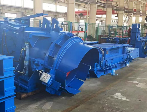
En una alta velocidad laminador de alambrón, el cabeza colocadora Es una de las últimas máquinas clave antes de la refrigeración controlada y la recogida de serpentines.. Su trabajo parece simple: guiar el alambrón caliente a través de un tubo de tendido curvo y formar anillos continuos en el transportador de enfriamiento. En producción real, sin embargo, muchos problemas con la forma de la bobina, enguijarrado, lanzamiento de cola, diámetro del anillo desigual, y el desgaste de la tubería de tendido están estrechamente relacionados con el cabezal de tendido, rollo de pellizco, tendido de ángulo de tubería, temperatura de la varilla, y coincidencia de velocidad.
Este artículo explica los fenómenos de producción comunes del cabezal de colocación de alambrón., métodos prácticos de tratamiento, y parámetros operativos útiles. Está escrito para operadores de laminadores., ingenieros de mantenimiento, ingenieros de procesos, y jefes de planta que quieren menos paros, forma de bobina más estable, y mejor calidad del producto en un molino de alambrón o laminador de acero.
nota practica: La mayoría de los problemas de la cabeza ponedora no son causados por un solo factor. Por lo general, provienen de una combinación de sincronización del rollo de pellizco., desviación de velocidad, desgaste de tuberías, ángulo de salida de tubería incorrecto, alta temperatura de acabado, altura inadecuada del transportador de enfriamiento, o tensión inestable entre el rodillo de arrastre y el cabezal de colocación.
1. Cómo funciona el cabezal tendido en un laminador de alambrón
En una moderna alta velocidad. laminador, El alambrón sale del bloque de acabado a muy alta velocidad.. Para tamaños pequeños como 5.5 milímetros o 6.5 mm, La velocidad de entrega puede alcanzar 90-110 m/s en muchas líneas de producción.. Luego, la varilla pasa a través de cajas de refrigeración por agua., rollos de pellizco, y la cabeza puesta. Dentro del cabezal de colocación, el tubo de tendido gira a alta velocidad y convierte la varilla recta en anillos helicoidales. Estos anillos caen sobre el transportador de enfriamiento y son transportados hacia adelante para un enfriamiento controlado..
El cabezal de colocación debe cumplir tres condiciones básicas:
- La varilla debe entrar suavemente en el tubo de tendido sin rayar., interferencia, o vibración.
- La velocidad de colocación de la tubería debe coincidir con la velocidad de laminado y el requisito de diámetro del anillo..
- Los anillos formados deben caer uniformemente sobre el transportador de enfriamiento con una separación estable y forma redonda..
Cuando estas condiciones no se cumplen, el molino mostrará síntomas obvios: extremo de la cola golpeando el disco de colocación, anillos grandes y pequeños, anillos ovalados, desplazamiento del anillo, quema de pipa, agrietamiento de tuberías, paquete de bobina inestable, o incluso adoquines alrededor del área de colocación.
2. Parámetros de funcionamiento típicos del cabezal de colocación de alambrón
Los valores exactos varían según el diseño del molino., grado del producto, disposición del stand, y proceso de enfriamiento. Los siguientes parámetros son referencias comunes para la producción de alambrón de alta velocidad.. Son útiles para comprobar si la ventana del proceso es razonable..
| Artículo | Rango común | Significado de la producción | Riesgo cuando es anormal |
|---|---|---|---|
| Diámetro del alambrón | 5.5–16mm, algunos molinos hasta 25 mm | Determina la velocidad de colocación., desgaste de la tubería, estabilidad del anillo | Los tamaños pequeños son más sensibles a la temperatura y la tensión. |
| Velocidad de acabado | 60–110 m/s para líneas de alta velocidad | Afecta directamente la velocidad de rotación de la tubería de tendido. | El desajuste de velocidad causa problemas en los anillos grandes/pequeños y en la cola |
| Temperatura de colocación | Generalmente entre 780 y 950 °C según el grado | Afecta la rigidez de la varilla y la forma del anillo. | Demasiado alto provoca anillos ovalados.; demasiado bajo puede aumentar la carga de la tubería |
| Diámetro del anillo | 850–1250 mm típico | Relacionado con el diseño de la tubería de tendido y el ancho del transportador. | El diámetro desigual provoca una mala forma del serpentín y una diferencia de enfriamiento |
| Tasa de avance del rollo de pellizco | 0.2–1,5% ajustado comúnmente | Mantiene la varilla estable antes de colocar la cabeza. | Demasiado plomo puede estirar la varilla; muy poco puede causar cola inestable |
| Colocación de material de tubería | Acero de aleación resistente al calor, tubo resistente al desgaste, tubería revestida de cerámica en algunos molinos | Afecta la vida útil y la suavidad de la superficie interior. | La ranura desgastada provoca anillos inestables y rayones en la superficie. |
3. Lanzamiento de cola a la cabeza tendidora
El lanzamiento de la cola significa que el extremo de la cola del alambrón no se puede descargar suavemente del tubo de tendido.. La cola pierde velocidad y fuerza., luego golpea el disco de colocación giratorio o el área de salida de la tubería. Los operadores suelen escuchar un sonido de impacto agudo.. En casos graves, el extremo de la cola se dobla, golpea la guía, daña la salida de la tubería, o provoca un adoquín cerca del cabezal de colocación.
Señales visibles en producción.
- El extremo de la cola no puede formar los últimos anillos normalmente..
- Los anillos finales de la bobina están desordenados o doblados..
- Se oye ruido de impacto en la salida del cabezal de colocación..
- Aparecen rayones en la cola en el disco de colocación o en la placa guía..
- La última parte de la bobina es difícil de recoger con cuidado..
Causas principales
- El rollo de pellizco se libera demasiado pronto. La cola pierde fuerza motriz antes de pasar completamente a través del tubo de tendido..
- La velocidad del rodillo de presión es demasiado baja. La cola tiene un impulso de avance insuficiente..
- El ángulo de lanzamiento de salida no es adecuado.. La cola encuentra una resistencia excesiva en la salida del tubo de tendido..
- La salida de la tubería está desgastada o deformada.. Un extremo desgastado puede enganchar o perturbar la cola..
- La velocidad de acabado cae bruscamente al final. Un mal seguimiento de la cola o un control de velocidad deficiente pueden reducir la energía cinética de la caña..
Métodos de tratamiento
| Acción | Práctica recomendada | Resultado esperado |
|---|---|---|
| Ampliar el tiempo de sujeción de la cola | Mantenga el rodillo de presión cerrado hasta que la cola tenga suficiente soporte para salir del tubo de tendido. | La cola sale suavemente; menos impactos de cola |
| Aumente ligeramente la velocidad de la cola del rodillo de arrastre | Ajustar con cuidado, generalmente dentro de un pequeño rango de derivación para evitar el estiramiento | Más impulso de la cola y mejor formación del anillo final. |
| Optimizar el ángulo de salida de la tubería | Reduce la resistencia al lanzamiento y suaviza el recorrido de la cola. | Menos colisión entre la cola y el disco giratorio. |
| Inspeccionar el estado de la salida de la tubería | Compruebe si hay rebabas, grietas, extremos aplanados, y pistas de desgaste profundo | Enganche reducido y descarga de cola más estable |
Un método de campo útil es grabar un video en cámara lenta de los últimos 2 a 3 segundos de la descarga de la cola.. Muchos problemas de cola son demasiado rápidos para juzgarlos a simple vista.. La revisión en video ayuda a confirmar si la cola pierde velocidad antes de la salida de la tubería o si está bloqueada en el ángulo de salida..
4. Anillos grandes y pequeños del cabezal tendido.
Los anillos grandes y pequeños hacen que el diámetro de la bobina cambie repetidamente en lugar de permanecer uniforme. Este es uno de los fenómenos más comunes en una alta velocidad. molino de alambrón. Afecta la apariencia de la bobina., uniformidad de refrigeración por aire, y manejo posterior. Para productos con estrictos requisitos de propiedades mecánicas, La distribución desigual del anillo también puede causar un enfriamiento desigual y fluctuaciones de propiedades a lo largo del serpentín..
Causas principales
- Tensión inestable entre el rodillo de arrastre y el cabezal de colocación. Esta es la causa más frecuente. Cuando la varilla se tira y se relaja alternativamente, cambios en el diámetro del anillo.
- Fluctuación de la velocidad del rodillo de arrastre. control electrico, deslizamiento del rollo, presión incorrecta, o la superficie desgastada del rodillo puede crear inestabilidad en la velocidad..
- La tubería de tendido tiene una ranura de desgaste profunda.. La varilla ya no se mueve suavemente dentro de la tubería.. Cambios de fricción durante la rotación..
- Coincidencia de velocidad incorrecta después del cambio de tamaño del producto. El ajuste de velocidad para 5.5 El alambrón de mm no se puede simplemente copiar en 8 milímetros o 10 mm de producción.
- Fluctuación de refrigeración por agua antes del cabezal de colocación.. La temperatura desigual cambia la rigidez de la varilla y la condición de fricción..
Métodos de tratamiento
- Mantenga estable la fuerza de sujeción del rodillo de arrastre. Evite marcas de deslizamiento en la superficie de la varilla..
- Compruebe la presión del rodillo prensador. Demasiado bajo provoca resbalones; demasiado alto puede marcar la varilla o aumentar la carga del rodamiento..
- Compruebe si la superficie del rollo está desgastada., pulido, o contaminado por incrustaciones.
- Verifique la relación de velocidad entre el bloque de acabado., rollo de pellizco, y poniendo la cabeza.
- Inspeccionar la pared interior del tubo de tendido.. Reemplácelo cuando surjan surcos profundos., grietas, o se encuentran adelgazamiento evidente.
- Después de reemplazar una tubería de tendido., comprobar el diámetro del anillo inmediatamente. Una tubería nueva puede requerir un ajuste fino de la velocidad.
En producción, una pequeña cantidad de fluctuación en el diámetro del anillo es normal. Pero si la bobina muestra patrones periódicos grandes-pequeños-grandes-pequeños, La primera comprobación debe ser la velocidad y la estabilidad de la tensión.. Si el patrón empeora después de varias series, Se debe comprobar el desgaste de las tuberías de tendido..
5. Anillos ovalados en el transportador de enfriamiento
Los anillos ovalados se encuentran a menudo al laminar alambrón de tamaño pequeño a alta temperatura de colocación.. A alta temperatura, el alambrón es más suave y más fácil de deformar después de salir del tubo de tendido. Si el anillo cae demasiado o golpea el transportador en un ángulo inadecuado, el anillo redondo se vuelve ovalado.
Los anillos ovalados no son sólo una cuestión de apariencia. Pueden causar apilamiento desigual, mala densidad de la bobina, flujo de aire irregular en el transportador de enfriamiento, y colección de serpentines inestable en la tina de reformado.
Causas comunes
- La temperatura de colocación es demasiado alta., especialmente para alambrón de 5,5 a 6,5 mm.
- La altura del transportador de refrigeración es demasiado baja, causando una gran distancia de caída.
- La trampilla de salida o el ángulo del deflector son demasiado pronunciados.
- Los anillos no aterrizan en la línea central del transportador..
- La velocidad del transportador no es adecuada para la distancia entre anillos..
Tratamiento practico
| Punto problemático | Método de ajuste | Efecto de producción |
|---|---|---|
| Alta temperatura de colocación | Incrementar el enfriamiento controlado antes de colocar el cabezal dentro de los límites metalúrgicos. | La varilla se vuelve más rígida; El anillo mantiene mejor la forma redonda. |
| Gran distancia de caída | Eleve la altura del transportador si el equipo lo permite., o ajustar las piezas de transición de salida | Deformación por menor impacto |
| Ángulo del deflector demasiado grande | Reduzca la inclinación para que los anillos caigan primero suavemente sobre la solapa., luego transfiera suavemente | Menos deformación ovalada y mejor posición central del anillo. |
| Aterrizaje descentrado | Ajustar la alineación del cabezal de colocación, posición de la solapa, y línea central del transportador | Anillos distribuidos uniformemente en el transportador. |
Para alambrón de acero con bajo contenido de carbono, La temperatura de colocación a menudo se selecciona según la velocidad de laminado., capacidad de enfriamiento, y microestructura requerida. Para alambrón con alto contenido de carbono, cable de acero del neumático, alambre de soldadura de acero, y acero de estampación en frío, El control de la temperatura debe ser más preciso porque el historial de enfriamiento afecta las propiedades mecánicas finales y la capacidad de embutición..
6. Los anillos se desplazan hacia un lado del transportador
Si los anillos caen constantemente hacia el lado izquierdo o derecho del transportador de enfriamiento, El problema suele ser la alineación mecánica o la dirección de salida.. Este fenómeno puede parecer menor al principio., pero puede causar un enfriamiento desigual, superposición de anillos, frotamiento del borde del transportador, y mala formación de bobinas.
Puntos de inspección
- Compruebe si la línea central del cabezal de colocación coincide con la línea central del transportador.
- Verifique la posición de instalación de la tubería de tendido..
- Compruebe si la salida del tubo de tendido se ha doblado debido a un impacto o sobrecalentamiento..
- Compruebe si la placa deflectora o la trampilla tienen un desgaste desigual.
- Verifique la distribución del ventilador de enfriamiento de aire. Un flujo de aire fuerte y desigual puede alterar los anillos de luz, especialmente tamaños pequeños.
Una prueba sencilla es marcar el centro de caída real de los anillos en el transportador durante el rodamiento estable.. Si el desplazamiento permanece constante para varias bobinas, La alineación mecánica debe corregirse.. Si el desplazamiento cambia con la velocidad o la temperatura, Los parámetros del proceso deben verificarse primero..
7. Desgaste de tuberías, Agrietamiento, y vida útil corta
El tendido de tuberías funciona en condiciones severas.: alta velocidad de rotación, contacto del hot rod, abrasión por incrustaciones de óxido, fuerza centrífuga, vibración, y ciclos térmicos. El desgaste de las tuberías es inevitable. El objetivo es hacer que el desgaste sea predecible y evitar fallas repentinas..
Principales mecanismos de desgaste.
- Desgaste abrasivo: Las incrustaciones de óxido de hierro actúan como partículas abrasivas entre el hot rod y la pared de la tubería..
- Fatiga térmica: El calentamiento y enfriamiento repetidos crean grietas en la superficie.
- Impacto mecánico: Los extremos de cabeza y cola golpean la tubería durante el roscado y la salida..
- Deslizamiento de alta velocidad: A alta velocidad de rodadura, Pequeños cambios de fricción producen mucho calor y desgaste..
No continúe utilizando una tubería de tendido con ranuras internas profundas., grietas de salida, adelgazamiento obvio, o vibración anormal. Una tubería averiada puede dañar el cabezal tendido, causar adoquines, y crear riesgos de seguridad alrededor del área de rodadura de alta velocidad.
Estándar de inspección recomendado
| Artículo de inspección | Condición normal | Condición de advertencia | Acción |
|---|---|---|---|
| pared interior | Desgaste suave, sin ranura afilada | pista profunda, superficie rugosa, acumulación de incrustaciones | Limpiar o reemplazar la tubería |
| Extremo de salida | Redondo, liso, ángulo correcto | Rebaba, grieta, aplastamiento, marca ardiente | Reparar sólo si está permitido; de lo contrario reemplazar |
| Fijación de tuberías | Ajustado, sin holgura | Pernos flojos, vibración anormal | Deténgase y corrija inmediatamente |
| Registro de servicio | La tendencia de desgaste es estable | La vida de repente se vuelve mucho más corta | comprobar materiales, enfriamiento, velocidad, y alineación |
Un hábito práctico de mantenimiento es llevar un registro de la vida útil de las tuberías por tamaño de producto., grado de acero, velocidad de rodadura, y tonelaje. Por ejemplo, la vida útil de la tubería en 5.5 mm la producción a alta velocidad puede ser mucho más corta que en 10 mm de producción porque la velocidad es mayor y la condición de contacto es más severa. Sin registros, Los equipos de mantenimiento a menudo reemplazan las tuberías demasiado tarde o demasiado pronto..
8. Adoquines de cabecera cerca de la cabecera de colocación
Los adoquines del cabezal cerca del cabezal de colocación son peligrosos porque la varilla se mueve a gran velocidad.. Es posible que el extremo de la cabecera no entre en la tubería de tendido., golpea la guía, o atascarse dentro de la tubería. Esto puede dañar el equipo e interrumpir el rodaje..
Posibles razones
- Mala forma de la cabeza por corte o cizallamiento aguas arriba.
- Alineación incorrecta de la guía antes del cabezal de colocación..
- El rollo de pellizco no está cerrado en el momento correcto.
- La entrada del tubo de tendido está desgastada., desalineado, o bloqueado por escala.
- La velocidad de balanceo no está sincronizada durante el enhebrado..
Medidas para reducir los adoquines de cabecera
- Asegúrese de que la cizalla volante corte un extremo de cabeza limpio y adecuado.
- Verifique todas las guías desde la salida de la caja de agua hasta la entrada del cabezal de tendido..
- Confirme el tiempo de cierre del rodillo de presión antes de probar el rodillo después del mantenimiento..
- Utilice una velocidad de enhebrado estable y evite cambios repentinos de velocidad..
- Elimine la acumulación de sarro en los tubos guía y en la entrada de la tubería de tendido..
Cuando se produce un adoquín en la cabeza repetidamente después de cambiar el tamaño del producto, no solo ajuste el cabezal de colocación. Comprueba todo el camino desde la última caja de agua., rollo de pellizco, tubo guía, desviador, y entrada del cabezal de colocación. Muchos adoquines de cabeza comienzan antes de la cabeza de colocación pero aparecen en la cabeza de colocación..
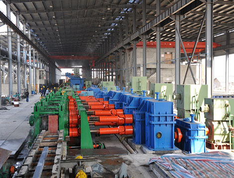
9. Espaciado deficiente entre anillos en el transportador de enfriamiento
El espacio entre anillos afecta la uniformidad del enfriamiento. Si los anillos son demasiado densos, el centro de la capa de la bobina se enfría lentamente. Si los anillos están demasiado abiertos, el área del transportador no se utiliza de manera efectiva y la distribución de la temperatura puede volverse desigual. El espaciado adecuado de los anillos depende de la velocidad de rodamiento., velocidad del cabezal de colocación, diámetro del anillo, y velocidad del transportador.
La relación básica es simple.: cuando la velocidad del transportador aumenta, el espacio entre anillos aumenta. Cuando la velocidad de laminación aumenta pero la velocidad del transportador permanece sin cambios, caen más anillos por unidad de longitud y el espaciamiento se vuelve más estrecho.
Ejemplo de referencia:
si un 6.5 mm de alambrón se lamina a 95 m/s y la circunferencia promedio del anillo es aproximadamente 3.14 m para un 1000 mm de diámetro del anillo, la cabeza de colocación se forma aproximadamente:
95 ÷ 3.14 ≈ 30 anillos por segundo
Si la velocidad del transportador de enfriamiento es 0.75 EM, El espacio teórico entre anillos a lo largo del transportador es de aproximadamente 0.75 ÷ 30 = 0.025 metro, o 25 mm por anillo. El espaciamiento real se verá afectado por la extensión del anillo., vibración del transportador, flujo de aire, y deformación del anillo.
Este cálculo no sustituye al ajuste de la planta., pero ayuda a los operadores a comprender por qué los cambios de velocidad del transportador deben coincidir con la velocidad de rodadura y el tamaño del producto..
10. Relación entre el rollo pellizco y la cabeza recostada
El rodillo de arrastre no es sólo un dispositivo de alimentación. Es la puerta de estabilidad antes del cabezal de colocación.. En muchos laminador de acero pauta, Los problemas de colocación se resuelven sólo después de corregir la configuración del rodillo de presión..
Configuración clave del rodillo de pellizco
- Presión de sujeción: Debe ser suficiente para agarrar la varilla pero no tan alto que cause marcas o deformación excesiva..
- Velocidad de avance: Por lo general, se establece ligeramente por encima de la velocidad de la varilla entrante para mantener una alimentación estable..
- Horario de apertura y cierre: Especialmente importante para el roscado de la cabeza y la salida de la cola..
- Condición de la superficie del rollo: Los rodillos desgastados o resbaladizos pueden causar una pérdida de velocidad oculta.
- Enfriamiento de panecillos: Un enfriamiento deficiente puede cambiar la condición de la superficie del rodillo y la vida útil del rodamiento..
| Problema con el rollo de pellizco | Síntoma probable de la cabeza acostada | Dirección correctiva |
|---|---|---|
| Baja presión | Corrimiento, anillos grandes y pequeños, mala cola | Aumente la presión gradualmente y revise las marcas de la superficie. |
| Presión alta | Marcas de varilla, vibración, posible distorsión de la sección | Reduzca la presión e inspeccione el perfil del rodillo. |
| Hora de cierre incorrecta | Cabeza de adoquín o primeros anillos inestables | Correct automation timing and sensor signal |
| Wrong opening time | Tail throwing and messy last rings | Ampliar el tiempo de sujeción de la cola |
11. Influencia de la temperatura en la calidad de la colocación
Temperature is one of the most important variables in laying quality. A hot rod is soft and easy to deform. A colder rod is stiffer but may increase friction inside the laying pipe. The correct temperature depends on steel grade and process route.
| Tipo de acero | Typical Laying Temperature Reference | Main Concern | Process Note |
|---|---|---|---|
| Low carbon wire rod | 850–950°C | Coil shape and scale control | Avoid too high temperature for small sizes |
| Medium carbon wire rod | 820–920°C | Mechanical property stability | Cooling rate must be controlled evenly |
| High carbon wire rod | 780–900°C | Pearlite transformation and drawability | Avoid uneven ring stacking and cooling variation |
| Acero de partida en frío | Controlled by grade specification | Surface quality and uniform structure | La colocación estable reduce la diferencia de enfriamiento local |
La temperatura debe medirse con un pirómetro adecuadamente calibrado.. Si la temperatura medida fluctúa bruscamente de una bobina a otra, comprobar la presión de la caja de agua, condición de la boquilla, velocidad de acabado, efecto desincrustante, y limpieza de la lente del pirómetro.
12. Lista de verificación diaria para la producción de cabezas ponedoras
Una breve lista de control antes de rodar puede evitar muchas paradas. El área del cabezal de colocación nunca debe tratarse como una sección de "funcionamiento hasta el fallo"., Porque las fallas aquí ocurren a alta velocidad y pueden afectar toda la línea de meta..
antes de rodar
- Comprobar la instalación de tuberías.
- Confirmar la alineación de la guía
- Comprobar la presión del rodillo prensador
- Confirmar receta de velocidad
- Incrustaciones limpias y materias extrañas
Durante el rodaje
- Estabilidad del diámetro del anillo del reloj
- Observar la condición de cola hacia afuera
- Escuche el impacto anormal
- Verifique el centro del anillo en el transportador
- Monitorear vibración y temperatura.
despues de rodar
- Inspeccionar el desgaste de la tubería
- Récord de tonelaje y tamaño de producto
- Check outlet burrs or cracks
- Review abnormal coil photos
- Plan replacement before failure
13. Tabla de resolución de problemas para decisiones de producción rápidas
The following table can be used as a quick reference on the mill floor. It links common laying head phenomena with likely causes and first actions.
| Phenomenon | Causa probable | First Check | Tratamiento |
|---|---|---|---|
| Tail hits laying disc | Tail lacks speed or support | Pinch roll opening time | Extend tail clamping, slightly increase tail lead, adjust outlet angle |
| Big and small rings | Unstable tension or worn pipe | Pinch roll speed and pipe groove | Stabilize pinch roll, correct speed ratio, replace worn pipe |
| Oval rings | High temperature or large falling distance | Laying temperature and conveyor height | Adjust cooling, reduce flap angle, center ring landing |
| Rings shift to one side | Misalignment or outlet deformation | Center line and pipe outlet | Align laying head, adjust deflector, inspect pipe |
| Head cobble | Bad head shape, error de guía, momento equivocado | corte de cizalla, camino guía, cerrar el rollo de pellizco | Mejorar el corte de cabeza, alinear guías, sincronización correcta |
| Corta vida útil de la tubería | Alto desgaste, material pobre, vibración, escala | Instalación y superficie interior de la tubería. | Utilice material de tubería adecuado, mejorar el enfriamiento y la alineación, récord de vida útil |
14. Buenos hábitos operativos que mejoran la estabilidad de la cabeza ponedora
La calidad de la colocación estable proviene de pequeños detalles repetidos en cada turno.. Los siguientes hábitos son simples pero efectivos en muchas operaciones de laminación de alambrón..
- No espere hasta que la forma de la bobina se deteriore antes de comprobar el tendido de la tubería..
- Después de cambiar el tamaño del producto, confirmar la velocidad de colocación, cable del rodillo de presión, velocidad del transportador, y receta refrescante juntos.
- Mantenga limpia el área alrededor del cabezal de colocación.. La acumulación de incrustaciones puede afectar la alineación de la guía y la disipación de calor..
- Capacite a los operadores para distinguir los problemas de tensión de los problemas de desgaste de las tuberías según el patrón de anillos..
- Utilice fotografías o vídeos cortos para registrar bobinas anormales.. Las notas escritas por sí solas a menudo no son suficientes.
- Verifique los sensores y la sincronización de la automatización con regularidad, especialmente después de paradas de mantenimiento.
- Nunca ignore las vibraciones anormales. a alta velocidad, Una pequeña vibración puede convertirse rápidamente en una falla mecánica..
15. Puntos prácticos para la selección y actualización de equipos
para un nuevo laminador de alambrón proyecto o una mejora de uno existente laminador, El cabezal de colocación debe seleccionarse junto con la velocidad de acabado., gama de productos, ancho del transportador de enfriamiento, y sistema de recogida de bobinas. Un cabezal tendido que funciona bien en 70 m/s puede no ser adecuado para un funcionamiento estable por encima 100 m/s sin margen de diseño adecuado.
Los puntos de selección importantes incluyen:
- Calidad de equilibrio dinámico: Las piezas giratorias de alta velocidad requieren un buen equilibrio para reducir la vibración.
- Conveniencia de reemplazo de tuberías por tendido: Un cambio de tubería más rápido reduce el tiempo de inactividad.
- Compatibilidad del material de la tubería: Diferentes grados y velocidades de acero pueden necesitar diferentes soluciones de tubería.
- Diseño de refrigeración y lubricación.: Los rodamientos y las piezas giratorias deben funcionar de forma fiable en condiciones de alta temperatura..
- Integración de controles: la cabeza puesta, rollo de pellizco, bloque de acabado, y el transportador debe estar sincronizado.
- Acceso de mantenimiento: Los operadores deberían poder inspeccionar áreas críticas de forma segura y rápida..
Recordatorio de producción final
El cabezal de colocación es el punto donde la velocidad de rodadura, temperatura de la varilla, alineación mecánica, desgaste de la tubería, y el proceso de enfriamiento se encuentran. Cuando tira la cola, anillos grandes y pequeños, anillos ovalados, o aparecen anillos descentrados, comprobar el sistema en su conjunto. Comience con el rodillo pellizco y haga coincidir la velocidad., luego inspeccionar la tubería de tendido, ángulo de salida, altura del transportador, y control de temperatura. Un cabezal de colocación estable proporciona una mejor forma de la bobina, enfriamiento más suave, menos adoquines, y una producción más fiable en cualquier laminador de alambrón moderno.