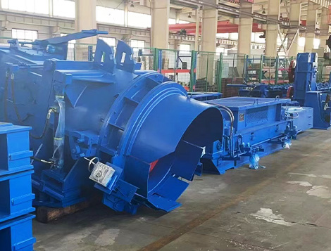
Le 320 le laminoir en porte-à-faux est un laminoir de taille moyenne à grande largement utilisé, conçu pour la production à grande vitesse de produits longs tels que les barres d'armature, fil machine, et petits profils. Par rapport au début 285 unités en porte-à-faux, il offre une capacité de roulement plus élevée, résistance structurelle améliorée, et une meilleure interchangeabilité, tout en gardant des tailles d'interface compatibles avec les lignes existantes.
Ce concept de conception sérialisée signifie que 320 le broyeur peut être configuré en plusieurs versions et capacités sur une plate-forme unifiée. Pour les ingénieurs de laminoirs, acheteurs d'équipement, et directeurs d'usine, cela permet d'élargir la ligne, la mise à niveau et la maintenance sont beaucoup plus faciles et plus économiques.
1. Positionnement du 320 laminoir en porte-à-faux dans les lignes de production
Dans une ligne typique de laminage de produits longs, le 320 le laminoir en porte-à-faux est généralement positionné dans:
- Supports intermédiaires pour laminoirs à barres et à tiges
- Supports de finition pour petites barres jusqu'à 25–32 mm
- Sections à grande vitesse dans les broyeurs continus ou semi-continus
Avec une bonne optimisation, le 320 l'unité peut rouler des barres en acier au carbone simples jusqu'à φ25 millimètres en standard, et jusqu'à φ32 millimètres pour des notes spécifiques et des modèles de réussite. La vitesse de roulement n'est généralement pas inférieure à 14 MS, et dans certaines applications de tiges à grande vitesse, la vitesse de travail réelle peut être légèrement plus élevée en fonction du moteur et des rapports de réduction.
2. Principaux paramètres techniques du 320 laminoir en porte-à-faux
| Article | Valeur typique | Remarques |
|---|---|---|
| Type de moulin | Cantilever, deux hauteurs | Disposition du stand horizontal ou vertical |
| Taille nominale | 320 mm | Fait référence à la plage de diamètres nominaux du cylindre |
| Max.. diamètre de roulement (standard) | φ25 millimètres | Barre en acier au carbone ordinaire |
| Max.. diamètre de roulement (optimisé) | Jusqu'à φ32 mm | Dépend de la conception du passe et de la qualité de l'acier |
| Vitesse de roulement | ≥ 14 MS | Pour un laminage continu à grande vitesse |
| Puissance du moteur principal (support unique) | ≈ 400-630 kW | Dépend du produit et du calendrier de réduction |
| Plage de diamètres de rouleaux | 280–360mm | Diamètre du corps du rouleau de travail |
| Longueur du canon du rouleau | ≈ 500-700 millimètres | Adaptable à différentes séquences de passes |
| Type de roulement | Roulements antifriction | Adapté à la vitesse et à la charge élevées |
| Gamme de produits typique | Barbe à barres, fil machine, barre à petite section | Acier au carbone et acier faiblement allié |
Les valeurs du tableau sont des valeurs techniques représentatives basées sur des pratiques industrielles courantes.. Des projets spécifiques devraient affiner ces paramètres en fonction de la capacité du four, taille des billettes, nuance d'acier, et objectif de production annuelle.
3. Concept de conception sérialisé du 320 rouleau
La conception sérialisée signifie une seule plateforme, de nombreuses variantes. Pour le 320 laminoir en porte-à-faux, ce concept couvre:
- Dimensions communes du boîtier de base et de l'interface
- Plusieurs rapports de démultiplication et combinaisons de modules d'engrenage
- Diamètres de rouleaux et longueurs de canon alternatifs
- Différents schémas de roulements et de lubrification
- Variantes de stands horizontaux et verticaux sur la même plateforme
L'objectif principal est de garder tout tailles d'interface externe inchangé: positions des boulons de fondation, centres de couplage, hauteurs des lignes de passage d'entrée et de sortie, et ports de refroidissement et de lubrification. Cela permet au nouveau 320 moulin à remplacer directement 285 ou des unités antérieures avec un minimum de travaux de génie civil et de révision de la tuyauterie.
3.1 Interfaces externes et interchangeabilité
Lors de la mise à niveau à partir d'un 285 à un 320 laminoir en porte-à-faux, une plante s'inquiète généralement:
- Si le nouveau stand s'adapte à l'ancienne fondation
- Si la hauteur de la ligne de passe change
- Si la longueur et l'angle d'accouplement universels sont toujours adaptés
- Que ce soit l'eau existante, les systèmes d'huile et d'air peuvent être réutilisés
Dans la conception sérialisée du 320 moulin, les dimensions suivantes sont généralement identiques à celles du 285 moulin:
| Élément d'interface | 285 (référence) | 320 sérialisé | Compatibilité |
|---|---|---|---|
| Modèle de boulon de fondation | Disposition existante | Même modèle conservé | Remplacement direct du support |
| Hauteur de la ligne de passe | Fixé | Conservé inchangé | Aucun changement aux tables à rouleaux et aux guides |
| Centre d'accouplement moteur | Ligne médiane d'origine | Même ligne médiane | Moteur et réducteur réutilisés |
| Entrée/sortie d'eau de refroidissement | Disposition des canalisations existante | Mêmes positions d'interface | Modification mineure ou aucune modification de la tuyauterie |
| Connexions de lubrification | Collecteur d'origine | Connexions compatibles | Station de lubrification existante utilisable |
En contrôlant ces dimensions d'interface, le 320 le broyeur peut être remplacé lors des arrêts de maintenance programmés avec un temps d'arrêt limité, ce qui est très précieux pour les usines fonctionnant à capacité annuelle élevée.
3.2 Options modulaires au sein du 320 série
Sous la même enveloppe extérieure, une série de configurations peut être proposée:
- Standard 320: Pour barres jusqu'à φ25 mm à ≥14 m/s
- Renforcé 320: Engrenage et boîtier renforcés pour une réduction plus élevée et un roulement de φ32 mm
- Grande vitesse 320: Roulements et lubrification optimisés pour un fonctionnement à long terme à vitesse élevée
- Version à roulement thermomécanique: Refroidissement et rigidité améliorés pour un laminage contrôlé des nuances faiblement alliées
Cette approche sérialisée signifie qu'une usine peut commencer avec une configuration de base, puis passer étape par étape à une vitesse plus élevée ou à un roulement de sections plus grandes sans reconstruire la ligne entière..
4. Optimisation structurelle du 320 laminoir en porte-à-faux
Pour supporter des forces de roulement et une vitesse plus élevées par rapport au 285 unité, le 320 le broyeur en porte-à-faux a été optimisé dans plusieurs parties clés.
4.1 Structure du logement et du caisson
Le carter du laminoir est l'épine dorsale de la cage de laminage. Pour le 320 moulin, les améliorations comprennent:
- Sections de paroi plus épaisses dans les zones de contraintes élevées près des cales des rouleaux
- Disposition optimisée des nervures pour répartir les charges de flexion et de torsion
- Rayons de congé améliorés dans les coins pour réduire la concentration des contraintes
- Utilisation d'acier moulé à haute résistance ou de structure en tôle d'acier soudée
L'analyse par éléments finis est couramment utilisée pour vérifier la rigidité du boîtier sous les forces de roulement de conception.. L'objectif est de maintenir l'allongement de l'écartement des rouleaux dans une plage contrôlée afin que la précision dimensionnelle de la barre ou de la tige soit maintenue., surtout à grande vitesse où les fluctuations de tension sont plus sensibles.
4.2 Dimensionnement des engrenages et optimisation de la transmission
Conduire un 320 rouleau en porte-à-faux à 14 m/s avec un rapport de réduction important exige des engrenages solides et fiables. La mise à niveau de 285 à 320 implique généralement:
- Module d'engrenage et largeur de face plus grands pour augmenter la résistance des dents
- Acier allié de qualité supérieure avec durcissement de surface pour les dents d'engrenage
- Profil de dent raffiné et finition pour réduire le bruit et les vibrations
- Rapport de démultiplication optimisé pour adapter la vitesse du moteur à la vitesse de rouleau souhaitée
Le calcul technique utilise les méthodes de conception d'engrenages AGMA ou ISO, compte tenu du couple transmis, facteur de surcharge, facteur dynamique, et marge de sécurité. Pour les usines qui prévoient de rouler des barres jusqu'à φ32 mm, il est courant de concevoir des engrenages avec une réserve de couple supplémentaire pour éviter les piqûres de dents et les dommages lors de charges maximales.
4.3 Boîte à rouleaux et résistance en porte-à-faux
La structure en porte-à-faux signifie qu'une extrémité du rouleau est soutenue et l'autre est libre pendant le fonctionnement. Cela simplifie le changement des rouleaux mais augmente également les charges de flexion sur la cale et le boîtier.. Le 320 la conception améliore la boîte à rouleaux en:
- Augmentation de la section transversale au niveau de la racine en porte-à-faux
- Sélection de roulements haute capacité avec une meilleure répartition de la charge
- Amélioration du verrouillage axial et radial des cales sur le boîtier
- Concevoir un mécanisme de réglage du rouleau plus rigide
Cette rigidité accrue permet non seulement de laminer des diamètres plus grands, mais réduit également la variation de l'ouverture du passage., ce qui améliore le contrôle de la jauge et la qualité de la surface, surtout pour les petites tailles à grande vitesse.
5. Amélioration des performances par rapport à 285 broyeurs en porte-à-faux
La mise à niveau de 285 à 320 les laminoirs en porte-à-faux apportent plusieurs avantages mesurables. Basé sur l'expérience pratique de nombreuses usines, les changements peuvent être résumés comme suit.
| Aspect | 285 broyeur en porte-à-faux | 320 broyeur en porte-à-faux | Amélioration typique |
|---|---|---|---|
| Max.. diamètre de la barre | φ20 millimètres | φ25 millimètres (jusqu'à φ32 mm optimisé) | 25–60 % d’augmentation de la taille des sections |
| Vitesse de roulement | ≈ 10-12 m/s | ≥ 14 MS | Vitesse de ligne et productivité plus élevées |
| Rigidité du boîtier | Inférieur | Plus haut, structure optimisée | Meilleur contrôle et stabilité de la jauge |
| Capacité des engrenages | Réserve de couple limitée | Capacité de couple plus grande | Réduisez l’usure des engrenages et les temps d’arrêt |
| Disponibilité du moulin | Modéré | Plus élevé en raison de composants plus solides | Fonctionnement plus stable à long terme |
Pour de nombreux producteurs de barres d’armature et de fil machine, ces améliorations se traduisent directement par un tonnage horaire plus élevé et une consommation d'énergie spécifique plus faible par tonne d'acier, surtout lorsqu'il est combiné avec une conception de passage et un réchauffage optimisés.
6. Scénarios d'application typiques et conception de lignes
Le 320 le laminoir en porte-à-faux est suffisamment flexible pour diverses configurations. Vous trouverez ci-dessous quelques scénarios pratiques qui permettent d'illustrer son utilisation..
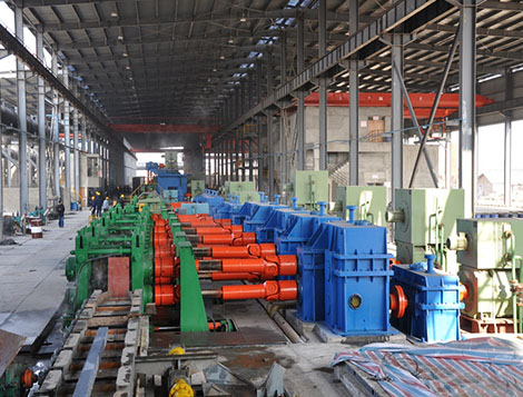
6.1 Ligne de production de barres d'armature à grande vitesse
Dans une ligne de barres d'armature à grande vitesse, billettes de 130×130 mm ou 150×150 mm sont chauffés dans un four de réchauffage puis laminés en ébauche, stands intermédiaires et de finition. Une disposition courante est:
- Ebauche: 2–3 tribunes (deux ou trois hauteurs)
- Intermédiaire: 4–6 stands utilisant 320 broyeurs en porte-à-faux
- Finition: 4–6 stands à grande vitesse (peut inclure 320 moulins)
Le 320 les stands des groupes intermédiaires et de finition sont chargés d'atteindre des vitesses de sortie élevées et d'atteindre les dimensions finales. Avec barres d'armature en acier au carbone ordinaire de qualité similaire à HRB400, les données typiques peuvent ressembler à:
| Paramètre | Valeur typique | Remarques |
|---|---|---|
| Taille des billettes | 150 × 150 × 6 m | Acier au carbone ordinaire, ~0,2–0,25 % C |
| Gamme de tailles de produits | Barres d'armature φ12–φ32 mm | Dépend de la conception du laissez-passer |
| Vitesse de ligne à la finition | 14–18 m/s | 320 les stands peuvent fonctionner à ≥14 m/s |
| Production horaire typique | 60–90 t/h | Varie selon la gamme de produits |
| Capacité annuelle | 300,000–700 000 t/an | Avec fonctionnement en plusieurs équipes |
Dans ce scénario, le 320 Le broyeur en porte-à-faux contribue à la formation stable des nervures et à une tolérance de diamètre serrée, qui sont essentiels à la qualité de l’acier de construction.
6.2 Broyeurs combinés à fil machine et petites barres
Une exigence courante dans de nombreuses régions est une ligne capable de produire à la fois du fil machine et des petites barres.. Dans de tels broyeurs combinés, le 320 le laminoir en porte-à-faux est souvent utilisé dans la section intermédiaire partagée:
- Pour fil machine: 320 les stands alimentent un bloc ou un groupe de finition à grande vitesse
- Pour bar: 320 les supports font office de fraises de finition jusqu'à φ25–φ32 mm
Cet arrangement à double objectif est intéressant car le même ensemble de 320 les stands peuvent gérer les deux itinéraires de processus en changeant les guides et les horaires de passage tout en conservant le même équipement de base.
6.3 Projets de mise à niveau: depuis 285 à 320
Pour les usines existantes équipées de 285 supports en porte-à-faux, mise à niveau vers le 320 la série est souvent le moyen le plus économique d’augmenter la capacité. Les étapes de mise à niveau typiques incluent:
- Enquête sur le tracé actuel de la ligne, état des fondations et des équipements
- Sélection des 320 modèle sérialisé (standard ou renforcé)
- Vérification de la correspondance des interfaces, y compris les raccords et les utilitaires
- Ajustement de la conception du passage pour utiliser pleinement une capacité plus élevée
- Remplacement prévu pendant l'arrêt, avec mise en service et réglage
Parce que le 320 est conçu en tenant compte de la compatibilité des interfaces, les travaux de génie civil sont minimisés et les interruptions de production sont raccourcies, ce qui est essentiel sur des marchés concurrentiels.
7. Détails du processus de roulement avec un 320 broyeur en porte-à-faux
Pour obtenir un fonctionnement stable et une qualité de produit élevée, conception de processus autour du 320 le laminoir doit être soigneusement étudié, y compris la conception du laissez-passer, matériau en rouleau, lubrification et refroidissement.
7.1 Conception des laissez-passer et calendrier de réduction
Le 320 le support permet une réduction relativement importante par passage par rapport aux supports plus petits, surtout dans la section intermédiaire. Cependant, pour maintenir un bon écoulement du métal et éviter les défauts internes, la pratique courante est:
- Répartir la réduction totale sur plusieurs passages au lieu de surcharger un seul stand
- Utilisez des séquences ovales-rondes ou carrées-ovales pour minimiser les fissures des bords
- Maintenir les facteurs d'allongement dans une plage raisonnable, généralement 1,2 à 1,4 par passage
Par exemple, lors du laminage d'une billette de φ150 mm en une barre de φ25 mm, le 320 les supports peuvent gérer les passes à mi-distance dans lesquelles la section transversale diminue d'environ 1 200 à 1 500 mm2 jusqu'à 400-600 mm2. Ceci équilibre la déformation entre les cages d'ébauche et de finition tout en utilisant les supports les plus résistants. 320 unités efficacement.
7.2 Gestion du matériau et de l'usure des rouleaux
En raison des forces de roulement plus élevées, sélection du matériau du rouleau pour un 320 le moulin est important. Les choix courants sont:
- Rouleaux en acier moulé allié: Bonne ténacité, utilisé dans les peuplements bruts et intermédiaires
- Rouleaux en fonte à haute teneur en chrome: Résistance à l'usure plus élevée, pour les passes de finition
En roulage à grande vitesse, la température de la surface des rouleaux et les fissures thermiques sont des problèmes clés. Un refroidissement adéquat et une usure contrôlée permettent des campagnes plus longues entre les réaffûtages, et affectent directement le coût de production par tonne. Le porte-à-faux plus solide du 320 supporte des rouleaux plus lourds si nécessaire, améliorant ainsi la durée de vie de la surface.
7.3 Conception de systèmes de lubrification et de refroidissement
Roulements et engrenages à charge élevée à l'intérieur d'un 320 le broyeur en porte-à-faux doit être refroidi et lubrifié efficacement. La pratique typique de l'ingénierie comprend:
- Lubrification forcée avec huile filtrée pour roulements et engrenages
- Circuits séparés pour les échangeurs thermiques huile propre et eau-huile
- Surveillance de la température et du débit pour éviter la surchauffe
À l'écart du rouleau, le refroidissement par eau doit être prévu pour refroidir à la fois les rouleaux de travail et le produit sans provoquer de choc thermique. Pour les petites dimensions à grande vitesse, la conception du collecteur et la disposition des buses sont particulièrement importantes pour éviter un refroidissement irrégulier et des défauts de surface.
8. Questions pratiques à longue traîne sur 320 rouleaux
De nombreux ingénieurs et acheteurs recherchent des informations très spécifiques avant de décider d'adopter le 320 laminoir en porte-à-faux. Vous trouverez ci-dessous plusieurs sujets détaillés souvent abordés dans la pratique.
8.1 Comment estimer la puissance du moteur pour un 320 support de moulin
Une estimation simplifiée de la puissance moteur requise P. d'une cage roulante est:
P ≈ (F × v) / (ou × 1000)
où:
- F = force de roulement (N)
- v = vitesse de sortie (MS)
- ou = efficacité (généralement 0,85 à 0,9)
Par exemple, si la force de roulement calculée dans un 320 le stand est 1,200 kN et la vitesse de sortie est 14 MS, en prenant η = 0.88:
P ≈ (1,200,000 × 14) / (0.88 × 1000) ≈ 19,090 kW
C'est la puissance mécanique au rouleau. Répartis entre les peuplements et prenant en compte des calculs de déformation plus détaillés, Les puissances nominales des moteurs de support individuels d'environ 400 à 630 kW sont typiques pour 320 moulins, en fonction de leur position dans la file et de la réduction totale attribuée.
8.2 Un 320 aciers alliés de poignée de laminoir?
Le 320 le laminoir en porte-à-faux est optimisé à l'origine pour l'acier au carbone ordinaire. Cependant, avec des matériaux en rouleaux appropriés, sélection des roulements et conception du refroidissement, il peut également laminer des aciers faiblement alliés tels que les aciers de construction et certaines qualités à ressorts. Pour une teneur en alliage plus élevée, le contrôle de la température et la conception des passes doivent être plus conservateurs, et la capacité de torsion du système d'entraînement doivent être soigneusement vérifiées.
En pratique, de nombreuses usines utilisent 320 signifie laminage thermomécanique de barres d'armature faiblement alliées, où le refroidissement et la déformation contrôlés dans les stands de finition fournissent les propriétés mécaniques requises sans traitement thermique coûteux.
8.3 Intervalles de maintenance et planification des pièces de rechange
Pour une aciérie de taille moyenne, planifier les cycles de maintenance pour le 320 le laminoir est important pour éviter les arrêts imprévus. Une approche pratique est:
- Tous les jours: Vérifier les niveaux d'huile, fuites, bruit anormal, refroidissement des rouleaux, et fixations de base
- Hebdomadaire: Inspecter les températures et les vibrations des roulements, examiner des échantillons d'huile pour engrenages à la recherche de particules métalliques
- Mensuel: Vérifier l'alignement, mesurer l'écart entre les rouleaux, vérifier l'état de l'accouplement
- Annuellement: Démontage partiel, inspection détaillée des engrenages, roulements et boîtier
La sérialisation est utile car le même type de cales de rouleaux de rechange, engrenages, et les roulements peuvent être utilisés sur plusieurs stands de la ligne, réduire les stocks et simplifier la gestion de la maintenance.
9. Conseils pratiques pour sélectionner un 320 laminoir en porte-à-faux
Lors de l'évaluation des fournisseurs et des modèles spécifiques au sein du 320 série, quelques points techniques pratiques méritent une attention particulière:
- Clarifier la gamme de produits cible: Décidez si l'objectif principal est les barres d'armature, fil machine, ou produits combinés, et quel diamètre maximum (φ25 ou φ32) est attendu.
- Vérifier les marges de sécurité structurelles: Demander les résultats des calculs ou la preuve que les engrenages, les roulements et le boîtier sont dimensionnés pour votre programme de roulement prévu avec un facteur de sécurité suffisant.
- Confirmer la compatibilité de l'interface: Pour les projets de mise à niveau, vérifier la hauteur de la ligne de passe, dimensions de base et centres d'accouplement par rapport aux dessins existants avant de passer la commande.
- Revoir la conception de la lubrification et du refroidissement: Assurez-vous que le broyeur est prêt à fonctionner à grande vitesse, avec des systèmes d'huile et d'eau appropriés, pas seulement les données de vitesse nominale.
- Envisager une expansion future: S'il est prévu de passer de φ25 à φ32 ou de 12 m/s à 14 MS, choisir dès le début une variante renforcée ou à grande vitesse pour éviter un remplacement prématuré.
En faisant soigneusement correspondre ces détails techniques aux objectifs de production réels, le 320 le laminoir cantilever peut déployer tout son potentiel, offrant un composant de base fiable et efficace pour les lignes modernes de laminage de produits longs.