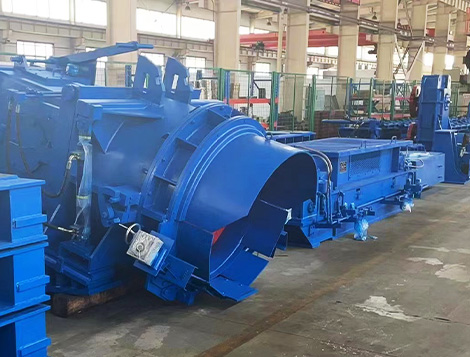
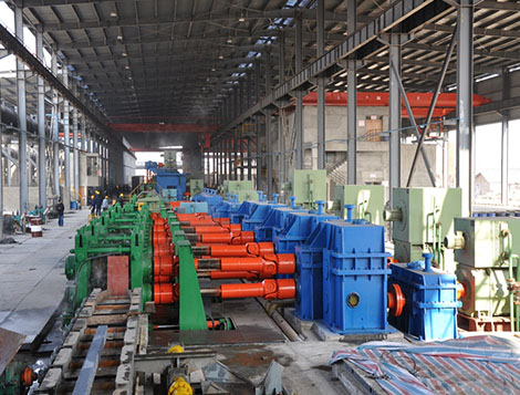
Введение: Основное определение & Основной состав универсальных прокатных станов
Прежде всего, универсальные прокатные станы являются основным оборудованием для производства сортового проката. Стандартная основная клеть стана включает одну пару горизонтальных валков и одну пару вертикальных валков.. Кроме того, оси четырех валков лежат в одной плоской плоскости.
Уточнить разделение функций, горизонтальные валки служат ведущими роликами. Вертикальные валки обычно работают как приводные ролики., в то время как некоторые модернизированные модели оснащают вертикальные валки независимыми системами привода.. Прежде всего, четыре валка могут сжимать заготовки с четырех направлений одновременно. Тем временем, горизонтальный стан с двумя валами сочетается с универсальной основной клетью в качестве вспомогательного обрезного стана.
Основная производственная линия универсальных прокатных станов
Во-первых, универсальные прокатные станы получили свое название благодаря мощности обработки нескольких изделий. Они могут прокатывать практически все основные типы сортового проката.. Обычная готовая продукция покрывает двутавровые балки., стальные рельсы, двутавровые балки, канал сталь, стальные шпунтовые сваи, U-образный стальной профиль, стальной равноугольный и неравноугольный стальной угол. Для другой вещи, они поддерживают гибкое серийное производство стали различных спецификаций.
Принцип работы, соответствующий вспомогательному обрезному станку
В общем, Полная универсальная линия прокатки включает в себя один универсальный основной стан и один двухвалковый горизонтальный обрезной стан.. Обе клети имеют реверсивную конструкцию прокатки для обеспечения непрерывной прокатки во время производства.. Кроме, вертикальные валки могут быть приводными или пассивными, однако операторы должны поддерживать одинаковую линейную скорость между горизонтальными и вертикальными поверхностями валков.. Более того, производители обычно размещают кромкообрезной станок до или после универсальной основной стойки для точной придания формы стальным кромкам..
Три уникальных преимущества универсальных прокатных станов
По сравнению с традиционными двухвалковыми или трехвалковыми секционными мельницами, универсальное прокатное оборудование имеет очевидные экономические и технические преимущества.
- Равномерная деформация и низкое внутреннее напряжение
Четыре валка образуют сложные интегрированные профили проходов.. Таким образом, все части стальных сечений получают одновременное сжатие.. На этом основании, разница скоростей в поперечном сечении заготовки резко сокращается. По очереди, готовая сталь имеет минимальное остаточное внутреннее напряжение и позволяет избежать дефектов растрескивания..
- Маленькие валки производят сталь большого сечения.
Универсальные станы используют валки малого диаметра для прокатки крупногабаритной стали.. Например, они производят широкополочные двутавровые балки и двутавровые балки с высокой стенкой.. Что еще более важно, обрабатывают двутавровые балки с нулевым внутренним уклоном по бокам полки, которые традиционные заводы не могут реализовать.
- Независимая регулировка увеличивает выпуск и сокращает потребление
Операторы регулируют уменьшение стенки и уменьшение полки отдельно.. Такая конструкция упрощает ежедневную калибровку мельницы.. По реальным производственным данным, универсальный прокатный механизм поднимает общий объем выпуска на 1.8 раз, повышает производительность оборудования на 10%, и сокращает расход рулонов на 20%.
Мировая история развития универсальных прокатных станов
Ранняя стадия зарубежных инноваций (1902–1970)
Первая в мире комплексная универсальная прокатная линия запущена в эксплуатацию в 1902 на сталелитейном заводе Arbed в Люксембурге. Тем не менее, двутавровые балки с широкими полками из этого раннего агрегата все еще имели скосы внутренних полок..
В 1908, Компания Bethlehem Steel в США построила первый завод по производству специальных широкополочных двутавровых балок, основанный на методе зеленой прокатки.. Этот стандарт требует согласованных универсальных фрез и комплектов кромкообрезных фрез.. Скоро в 1914, Компания Peine AG из Германии скопировала эту технологию и открыла свою базу по производству двутавровых балок..
Позже в 1955, Европейское сообщество угля и стали разработало стандартную серию балок IPE.. В 1957, Peine Steel выпустила первую партию балок IPE. Даже по 1970, Двутавровые балки по-прежнему занимали основную долю мирового производства сортового проката..
Глобальный бум популяризации после 1960-х годов
После 1960-х годов, Расширение сталелитейной промышленности во всем мире способствовало быстрой модернизации универсального стана. Большинство металлургических предприятий реконструировали старые рельсобалочные станы с использованием нового универсального оборудования.. Япония широко приняла этот путь обновления..
Между 1961 и 1972, Японские металлургические предприятия модернизировали три крупносортных завода и один рельсобалочный завод за счет импортных универсальных станов.. Уже как 1965, Япония добилась массового производства двутавровых балок. К концу 1960-х годов, мир принадлежит 74 станы тяжелого проката, 24 рельсобалочные станы и 12 специализированные линии прокатки широкополочной балки.
История местного развития универсальных прокатных станов в Китае
Ограничено первоначальными техническими и политическими ограничениями, В Китае долгое время не было развитой универсальной технологии прокатки.. Отечественные заводы не могли самостоятельно производить качественную горячекатаную двутавровую балку..
В июле 1998, Мааньшань Железо & Сталелитейщик ввел в эксплуатацию импортные универсальные станы и прокатал первую в Китае качественную двутавровую балку. Эта веха открыла новую главу отечественного производства двутавровых балок.. После, Стальная линия, Жичжао Сталь, Jinxi Iron and Steel и другие производители сортового проката последовательно представили за рубежом универсальные линии по производству прокатных станов.. К 2007, Количество отечественных универсальных мельниц быстро росло, и большая часть оборудования зависела от дорогого иностранного импорта..
Ключевой поворотный момент наступил 2003. А 300 Линия по производству двутавровых балок, спроектированная и изготовленная компанией Tianjin Zhongzhong Heavy Technology, запущена в эксплуатацию. Это событие ознаменовало официальный ввод в эксплуатацию первого в Китае универсального прокатного стана отечественной разработки..
Впоследствии, универсальные мельницы собственной разработки для Далянь Чжэнда, Таншань Шэнда, Металлургические заводы Аньшань Зычжу и Аньшань Баодэ начали работу один за другим. Как результат, В Китае реализована полная локализация универсального прокатного оборудования, охватывающего спецификации двутавровых балок полной серии от 100H до 600H..
1. Ассортимент продуктов & Объем производства
1.1 Прокатные марки стали
- Типы материалов: Обычная углеродистая сталь, низколегированная конструкционная сталь, высококачественная углеродистая конструкционная сталь
- Типичные оценки: Q195, Q235 и другая стандартная конструкционная сталь
1.2 Полные характеристики продукта
- Узкая полка двутавровая балка: 100×50, 125×60, 150×75, 175×90, 200×100
- Средняя полка двутавровая балка: 150×100
- Широкая полка двутавровая балка: 100×100, 125×125
- I-Beam: 8# ~ 22#
- Швеллер стальной: 5# ~ 20#
- Угловая сталь: 5# ~ 12.5#
2. Полный состав универсального поезда прокатного стана
Полная универсальная линия мельницы содержит несколько основных модулей.:
Универсальная основная мельница, суппорт шпинделя, универсальный шпиндель мельницы, комбинированный редуктор, главная муфта двигателя, главный приводной двигатель.
3. Технические данные универсального прокатного стана с линией короткого напряжения & Структура
Основная функция
Он прокатывает промежуточные стальные заготовки в квалифицированный готовый сортовой прокат по установленным технологическим правилам горячей прокатки..
Тип мельницы
Универсальный прокатный стан с короткой линией напряжения
Номинальная сила качения
- Максимальная сила прокатки горизонтального валка: 3000 кН
- Максимальная сила прокатки вертикального валка: 1500 кН
Размеры роликовых колец
- Горизонтальное роликовое кольцо: φ830/φ720 × 220 мм
- Вертикальное роликовое кольцо: φ540/φ470 × 185 мм
Регулируемый диапазон расстояния до центра рулона
- Горизонтальный рулон: 850–720 мм
- Вертикальный рулон: 790–565 мм
Диапазон осевой регулировки горизонтального валка
±4 мм (регулируется как для верхних, так и для нижних горизонтальных валков)
Диаметр горизонтальной шейки ролика
Общая структура мельницы
Универсальная мельница состоит из горизонтальных валковых агрегатов., вертикальные роликовые агрегаты, опорные рамы, устройства регулирования зазора между валками, тележки для смены рулонов, направляющая балка и основание фрезы.
Прежде всего, валковые узлы и устройства регулирования зазора образуют стержневую кассету мельницы. Следующий, Технические специалисты соединяют стержневой картридж со встроенными трубопроводами с помощью стопорных болтов, образуя целостный корпус мельницы.. В конце концов, весь корпус мельницы крепится к основанию с помощью гидравлических цилиндров с запорными болтами.
3.1 Горизонтальный & Детали сборки вертикального рулона
Конструкция горизонтального рулонного агрегата
В комплект горизонтальных валков входят горизонтальные валки., подшипник качения + колодка в сборе, группы рулевых тяг и опорные рамы. Верхние и нижние валки устанавливаются на опорные подушки с подшипниками качения со стороны привода и со стороны эксплуатации.. В каждой колодке имеются завинчивающиеся гайки.. Четыре тяги проходят через четыре промежуточных опорных гнезда и соединяют вместе верхнюю и нижнюю опоры.. Эта компоновка образует систему роликов с короткими напряженными линиями..
Поскольку конструкция исключает тяжелые корпуса мельниц, Пути передачи напряжений проходят только через тяги и встроенные гайки. Таким образом, длина линии напряжения значительно сокращается, а пружинение фрезы эффективно снижается.. Более того, Подушки, соединенные с рулевой тягой, оптимизируют напряженное состояние подшипника, повысить грузоподъемность подшипника и продлить срок службы.
Схема соответствия подшипников
- Радиальная нагрузка: Четырехрядные цилиндрические роликоподшипники повышенной жесткости.
- Осевая нагрузка: Двухсторонние упорные конические роликоподшипники
Кроме того, сферические колодки компенсируют неравномерное распределение усилий по каждому ряду тел качения, продлевая срок службы подшипников.. Для снижения нагрузки на навинчивающие устройства и уменьшения истирания рулевой тяги., Опоры рулевых тяг принимают конструкции подшипников качения. Лабиринтные и каркасные сальники предотвращают попадание охлаждающей воды и грязи в камеры подшипников..
Баланс броска & Осевая регулировка
Встроенные эластичные тарельчатые пружинные амортизаторы внутри рулевых тяг устраняют зазор в резьбе между рулевыми тягами и гайками.. Такая конструкция позволяет избежать радиального биения валков, вызванного зазорами в резьбе.. Тем временем, Устройства осевой регулировки устанавливают внутри рабочих боковых подушек верхних и нижних валков.. Ручные червячные косозубые передачи вращают резьбовые втулки, толкая упорные подшипники., внутренние втулки и ролики для точного осевого позиционирования. Втулки с контррезьбой устраняют зазор резьбы и предотвращают ее ослабление, обеспечивая точное выравнивание проходов..
Вертикальный роликовый подшипник & Баланс Дизайн
Вертикальные валки оснащены двухрядными коническими роликоподшипниками, способными выдерживать как радиальные, так и осевые нагрузки.. Водяные уплотнения VD и каркасные уплотнения блокируют воду и загрязнения.. Сходным образом, Встроенные тарельчатые пружины рулевой тяги устраняют зазор резьбы винта и предотвращают радиальное биение вертикального ролика..
3.2 Независимый горизонтальный & Устройства регулировки вертикального зазора между валками
Блок регулировки горизонтального зазора между валками
Основные компоненты: Гидравлический двигатель, трансмиссионный вал, схватить, водить машину & Червячные редукторы рабочей стороны. В червячных редукторах используются сварные корпуса с калиброванными циферблатными шкалами..
На каждую боковую коробку устанавливается один червяк и пара червячных передач.. Гидравлические двигатели приводят червяки во вращение червячных передач.. Шестерни под червячными шестернями входят в зацепление с внутренними шлицевыми зубчатыми втулками для поворота тяг и регулировки горизонтальных зазоров между валками.. Операторы считывают положения завинчивания с помощью циферблатных шкал на вершинах рулевых тяг.. Гидравлическая муфта на рабочей стороне поддерживает одностороннюю независимую регулировку для поддержания уровня горизонтального крена..
Блок регулировки вертикального зазора между валками
Основные компоненты: Гидравлический двигатель, набор червячных передач, завинчивающаяся гайка и винт. Гидравлические двигатели приводят червяки во вращение червячных передач.. Внутренняя резьба на червячных передачах соответствует завинчивающимся винтам, позволяющим перемещать винты вперед или назад и изменять вертикальные зазоры между валками.. Вертикальные ролики со стороны управления и со стороны привода поддерживают раздельную регулировку.. Кроме гидропривода, резервное устройство с ручной регулировкой устанавливается для экстренного использования. Операторы проверяют вертикальное положение рулонов с помощью шкал..
3.3 Сварная основа мельницы & Система горизонтального перемещения мельницы
Основание мельницы представляет собой цельную сварную стальную конструкцию, закрепленную на бетонном фундаменте с помощью анкерных болтов.. Он оснащен двумя ключевыми гидравлическими агрегатами.: цилиндры блокировки мельницы и цилиндры перемещения мельницы.
- Запорный цилиндр мельницы: Блокировка дисковой пружины + режим гидравлического выпуска, прочно закрепляет корпус мельницы на основании во время производства. Мельница не сможет двигаться, пока стопорные цилиндры полностью не освободятся..
- Поворотный цилиндр мельницы: Гидравлический привод осуществляет горизонтальное смещение мельницы.. Поскольку эта линия использует многопроходную прокатку с фиксированной осевой линией прокатки., станы должны двигаться горизонтально, чтобы переключать разные проходы валков.
Двойная функция механизма перемещения: Переключатель прохода & Полная замена рулона картриджа
Опорная каретка шпинделя соединяется с корпусами мельниц через штифтовые гидроцилиндры и соединяет перемещающие цилиндры через вставные пластины.. Поворотные гидравлические цилиндры толкают все корпуса мельницы горизонтально.. Когда мельницы достигают целевых позиций, запирающие цилиндры сбрасываются, чтобы снова заблокировать устройство.
Для полной замены рулона картриджа: Запорные цилиндры освобождаются первыми. Поворотные цилиндры толкают каретку шпинделя и корпуса мельниц в сторону рабочей стороны к станции смены валков.. Штифтовые цилиндры втягивают штифты, затем перемещающие цилиндры тянут каретки шпинделей назад на сторону привода, чтобы разделить шпиндельные головки валков и универсальные шпиндели.. После расставания, тележки для смены валков быстро заменяют старые и новые кассеты мельниц.
4. Опорная каретка шпинделя
Основная цель
Баланс общего веса универсальных шпинделей, зажим верхний & нижние шпиндели при смене валков, и постоянно поддерживать горизонтальное положение втулки шпинделя.
Тип структуры
Портальная рама с взаимной балансировкой веса между верхним и нижним шпинделями, а также пружинной буферной конструкцией.. Операторы регулируют центральное расстояние верхней/нижней каретки симметрично относительно линий прокатки, чтобы соответствовать переменному расстоянию между центрами роликов..
Каретки устанавливаются на основания стана. Цепи и фиксированные шкивы соединяют вместе верхние и нижние опорные подушки.. Опоры подшипников качения удерживают универсальные шпиндели внутри подъемных направляющих, обеспечивая непрерывную поддержку.. Взаимная балансировка веса исключает дополнительную нагрузку на подшипники со стороны привода вальцов и стабилизирует нагрузку на устройство балансировки валка.. Гидравлические штифтовые цилиндры обеспечивают автоматическое соединение и разделение кареток и корпусов мельниц.. Подшипники каретки смазываются консистентной смазкой..
5. Универсальные шпиндели для мельниц
Модель: Универсальный шпиндель с телескопическим поперечным валом
Количество: Два шпинделя на становой поезд
Взаимозаменяемость: Шпиндели одинаковой спецификации могут свободно заменять друг друга.
Телескопический ход: ±350 мм
6. Комбинированная коробка передач
Комбинированная коробка передач объединяет редукторы и седло шестерни в один единый блок.. Два выходных вала соединяют универсальные шпиндели стана с раздельным приводом верхних и нижних горизонтальных валков..
7. Муфта двигателя главного привода
Тип: Зубчатая муфта барабана с полностью безопасным защитным корпусом.
8. Стандарт системы смазки
- Роликовые подшипники: Централизованная смазка консистентной смазкой
- Мельничные футеровки и завинчивающиеся гайки: Ручная заправка смазки
9. Встроенные средние трубопроводы
Все гидравлические, трубопроводы смазки и охлаждающей воды располагаются на корпусах мельниц. Двойные фланцы или быстроразъемные соединения применяются на всех точках соединения трубопровода для облегчения разборки и обслуживания..
10. Марки материалов ключевых компонентов & Правила термообработки