تتطور العوارض H المدرفلة على الساخن من العوارض I التقليدية بعد التصميم الهيكلي الأمثل. إنها تنتمي إلى فولاذ القسم الأخضر الاقتصادي ذو الأداء الميكانيكي المتميز. لتبدأ, تمتلك عوارض H أبعادًا عقلانية للمقطع العرضي واستطالة معدنية موحدة أثناء التدحرج, لذلك يبقى الضغط الداخلي المتبقي منخفضًا. بالمقارنة مع الحزم I القياسية, تتميز الحزم H بمعامل قسم أكبر, أخف وزنا ذاتيا, قدرة تحمل أقوى واستهلاك أقل للصلب الخام.
في السنوات الأخيرة, تكتسب الحزم H تطبيقًا واسعًا عبر قطاعات البناء الفولاذية الثقيلة. تغطي السيناريوهات النموذجية آلات الرفع الكبيرة, أسس المعدات الثقيلة, إطارات دعم طويلة المدى, منصات النفط البحرية ومشاريع هندسة الطاقة. تركيبها السهل وخصائصها الميكانيكية الموثوقة تجعلها مادة هيكلية مفضلة.
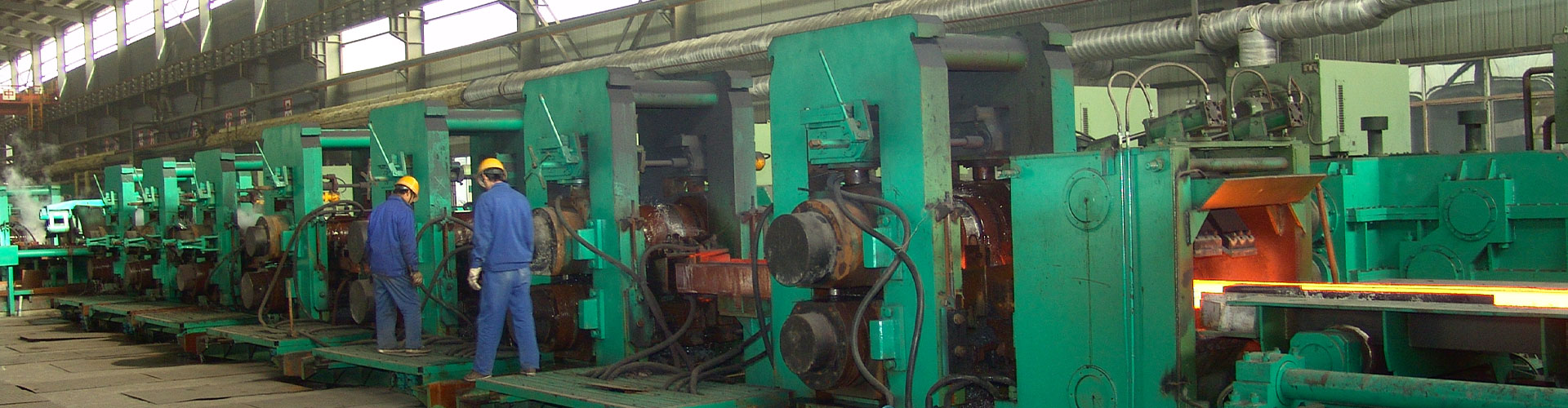
تم إطلاق خط إنتاج الشعاع H الكبير لشركة Laigang في سبتمبر 2005. تم استيراد معدات الدرفلة الأساسية وتكنولوجيا التصنيع بالكامل من شركة SMS Meer الألمانية, مع الانتاج السنوي المصمم ل 1 مليون طن. للفراغات الخام, يعتمد الخط ألواح صب مستمرة رفيعة جدًا على شكل شبكي تقريبًا, والتي تعد من بين المواصفات الفارغة الأكثر تقدمًا في العالم. في أثناء, فهو يطبق تقنيات متقدمة ناضجة: تسخين رقمي واسع اللهب ودحرجة ترادفية مدمجة X-H. تدعم هذه العمليات الكفاءة العالية, صناعة الصلب الموفرة للطاقة ومنخفضة التكلفة.
يمكن لخط الإنتاج هذا تصنيع كمرات H تتراوح من الارتفاع 250 مم إلى الارتفاع 1000 مم, يقترب من الوصول إلى الحد الأقصى العالمي لمواصفات إنتاج الشعاع H. ومع ذلك, يؤدي تقادم المعدات على المدى الطويل والفقد التدريجي لدقة الأدوات المتداول إلى حدوث عيوب متكررة في المنتج أثناء التدحرج. تشمل العيوب الشائعة انحراف قطعة العمل, الانحناء والتسامح الأبعاد غير المستقر. والأسوأ من ذلك, لا يمكن لتعديل العملية البسيطة القضاء على العديد من هذه العيوب بشكل كامل. تقيد هذه المشكلات بشدة جودة العارضة H النهائية والإنتاج المستقر المستمر.
1 تكوين نظام الأدوات لمطاحن الدرفلة العالمية
يتبع التدفق المتدحرج للعارضة H في Laigang مرحلتين رئيسيتين للتدحرج. أولاً, مطحنة التخشين ذات ارتفاعين (مطحنة بي دي) لفات الألواح الخام إلى الفراغات المتوسطة. التالي, مجموعة مطحنة جنبا إلى جنب (TM) يجري دحرجة مستمرة عكسية لتشكيل عوارض H جاهزة. تحتوي مجموعة TM على مطحنتين عالميتين ومطحنة واحدة.
تمر قطع العمل عبر UR – E – UF لتمرير التدحرج الأول. بعد ذلك, the line reverses material direction, والفراغات تمر عبر UF – ED – UR بالتتابع. بعد المتداول جنبا إلى جنب المتكررة, خروج عوارض H النهائية من مطحنة UF.
تتكون كل من المطاحن العالمية UR وUF من مجموعة واحدة من اللفات الأفقية التي تعمل بمحرك ومجموعة واحدة من اللفات العمودية السلبية. وظيفتها الأساسية هي تقليل سمك شبكة العارضة والشفة. تقوم مطحنة الحواف ذات الحافة المزدوجة ED بمعالجة أطراف الحافة فقط للتحكم في ارتفاع الحافة النهائي. باختصار, دقة الأبعاد, تعتمد حالة التشكيل والتشوه المعدني للعوارض H بشكل أساسي على أداء المطاحن العالمية UR وUF.
تشتمل مطحنة الدرفلة الشاملة الكاملة على ثلاث مجموعات أساسية: نظام لفة أفقية, نظام اللفة العمودية ونظام حماية التوجيه. تشكل اللفات الأفقية والرأسية معًا نظام التمرير على شكل حرف H, الذي يتصل مباشرة بالفراغات ويكمل تشوه البلاستيك. لذلك, تحدد دقة تحديد موضع التجميع التسامح الأبعاد النهائي للعوارض H.
على الجانب الآخر, يقوم حراس التوجيه بتغذية الفراغات إلى لفات بسلاسة وتوجيه الفولاذ النهائي إلى خارج المصنع. أنها تمنع التواء الشريط, التحول الأفقي ولف اللف أثناء الإنتاج. لهذا السبب, تؤثر دقة الأبعاد لحراس التوجيه بشكل مباشر على حالة تشكيل قطعة العمل مثل الانحناء والالتواء.
1.1 نظام اللفة الأفقية للمطاحن العالمية
The horizontal roll system combines roll chocks and horizontal work rolls. تحتوي كل مجموعة من الوصلات على ألواح ضغط, لوحات انزلاقية محورية, اللوحات المنزلقة الرئيسية والمباني المتطابقة. يتصل أحد جوانب نظام اللفة بمحرك الدفع الرئيسي, بينما تتلاءم الألواح المنزلقة بإحكام مع غلاف المطحنة لتشكل وحدة متكاملة.
أي انحراف في حجم المكون, سيؤدي التآكل المفرط أو ضعف دقة التجميع إلى تشويه مجموعة الساندة بأكملها. ينتقل الخطأ إلى اللفات الأفقية المثبتة ويؤدي في النهاية إلى حدوث عيوب في الأبعاد على العوارض H المدرفلة.
1.1.1 لفة لوحات الضغط تشوك
يؤدي التآكل غير المتساوي أو السُمك غير المتناسق بين ألواح الضغط اليمنى واليسرى إلى انحراف الارتفاع على جانبي الساندة. نتيجة ل, تميل اللفات الأفقية قليلاً أثناء التشغيل. التمريرة على شكل H تفقد شكلها المتماثل, وتصبح فجوة اللفة غير متساوية: يحمل أحد الجانبين فجوة أوسع بينما يضيق الجانب الآخر.
أثناء المتداول, يجلب جانب الفجوة الضيقة استطالة معدنية أكبر, وينتج جانب الفجوة الواسعة استطالة أصغر. تنحني قطعة العمل نحو الجانب المنخفض الاستطالة وتشكل عيوب إزاحة الرأس.
فضلاً عن ذلك, تترك ألواح الضغط البالية فجوات بين الألواح والأوقاف. وبصرف النظر عن الميل لفة, يتشوه منحنى الصلابة الإجمالي لمجموعة البكرات بشكل سيئ. يفقد التمرير المتدحرج الهندسة القياسية, مما يؤدي إلى التسامح الأبعاد غير المستقر للصلب النهائي.
1.1.2 لفة لوحات انزلاقية محورية
يؤدي التآكل المستمر إلى تقليل العرض الإجمالي للألواح المنزلقة المحورية. يتشكل الخلوص الزائد بين الأوتاد ومساكن المطاحن. يتحرك الساندة بالكامل بشكل محوري داخل السكن, مما يقلل من السكتة الدماغية الفعالة للتعديل المحوري عبر الإنترنت. يواجه المشغلون صعوبات في ضبط شكل وأبعاد قطعة العمل.
علاوة على ذلك, تؤدي الألواح المنزلقة الأوفست إلى حركة محورية للساندة. تفشل الخطوط المركزية للبكرات الأفقية العلوية والسفلية في المحاذاة. تقوم أعمال المعايرة بتوزيع الانحراف الكلي على أحد جانبي المكبس الهيدروليكي وتقطع شوط المكبس المقابل القابل للتعديل. صعوبة التكيف ترتفع بشكل حاد, ويصبح التحكم في البعد المستقر مستحيلاً.
1.1.3 لفة تشوك لوحات الانزلاق الرئيسية
يفشل التآكل الشديد على الألواح المنزلقة الرئيسية في قفل الأوتاد بقوة داخل الهيكل. تفقد اللفات الأفقية موضعها الموثوق وتزيد من صعوبة الضبط. ينخفض u200bu200bثبات التدحرج بشكل ملحوظ. في نفس الوقت, ينقل تأثير التدحرج الدوري اهتزازًا إضافيًا إلى نظام القيادة بأكمله ويضر باستقرار التشغيل.
1.2 نظام اللفة العمودية لمطاحن الدرفلة العالمية
يشتمل نظام اللف العمودي على بكرات العمل العمودية وصناديق اللف العمودية. يتم تثبيت الرولات العمودية داخل صناديق مخصصة لذلك, ويتناسب الصندوق بأكمله مع غلاف المطحنة. جنبا إلى جنب مع لفات أفقية, يقومون ببناء ممر تشوه الشعاع H الكامل. تقوم أسطح اللف العمودية بمعالجة حافتي العوارض H. هناك عاملان رئيسيان يحددان دقة أدوات اللف العمودي: دقة تحديد موضع اللفات الرأسية وتفاوت التركيب بين صناديق اللف العمودية وأغطية المطحنة.
1.2.1 دقة أبعاد الموضع للفات العمودية
يشير هذا المؤشر إلى خلوص التجميع بين البكرات العمودية وصناديقها, تغطي نقطتي تحكم أساسيتين: الفجوة المناسبة بين نافذة الصندوق واللفائف العمودية, والبعد الأساسي لصناديق اللف العمودية.
1.2.1.1 تركيب الفجوة بين نافذة صندوق اللف العمودي واللفائف العمودية
التخليص المفرط (أ1 و أ2) يخلق داخل نافذة صندوق اللفات مساحة إضافية قابلة للتحريك للفات الرأسية. تغوص اللفات العمودية للأسفل وتشكل فجوة على شكل قرن. تتقلص الفجوة بين اللفات الرأسية واللفة الأفقية العلوية, بينما تتسع الفجوة بين اللفات العمودية واللفة الأفقية السفلية. في الإنتاج, تُظهر عوارض H النهائية حوافًا علوية رفيعة وحواف سفلية سميكة. يؤدي الانحراف الشديد إلى إلغاء المنتجات.
1.2.1.2 البعد الأساسي لصناديق الرول العمودية
تؤدي الأبعاد الأساسية المنحرفة إلى فشلين نموذجيين. أولاً, لا يمكن ربط أسطح البكرات الرأسية بشكل كامل بالبكرات الأفقية أثناء المعايرة, وتمرير المعايرة فشل تماما. ثانية, يؤدي التسامح المناسب غير المتطابق إلى تشويه المفصل بين خطوط الأنابيب الصندوقية وموصلات رأس الأسطوانة. يتسرب ماء التبريد بشكل كبير ويضعف أداء التبريد العمودي.
بجانب, تشكل اللفات الرأسية المائلة داخل الصناديق فجوات على شكل قرن. تنتج قطع العمل رؤوسًا منحنية لأعلى أو لأسفل, وعيوب سمك الحافة غير المستوية (قمة رقيقة, قاع سميك) يظهر مرارا وتكرارا, مما قد يؤدي إلى خردة جماعية.
1.2.2 الحجم الملائم بين صناديق اللف العمودية ومساكن المطحنة
إذا كان البعد الخارجي لصناديق اللف العمودية صغيرًا جدًا, لا يستطيع المشغلون دفع الصناديق إلى أغلفة المطاحن بسلاسة. إذا كان البعد كبير الحجم أو الارتفاع الأفقي يختلف على الجانبين, تميل القوائم العمودية بعد بدء تشغيل المعدات. سمك الحافة العلوية والسفلية يصبح غير متناسق, وتسبب عيوب رأس الانحناء الخطيرة تكديس الفولاذ بين حوامل المطاحن.
1.3 نظام حراسة الدليل
تعتمد هذه المطحنة العالمية واقيات توجيه مثبتة على شعاع. تعمل الأقواس الثابتة على العوارض المتقاطعة على قفل جميع وحدات التوجيه. هناك عاملان يسيطران على دقة نظام التوجيه بأكمله: عرض & طول حراس الدليل, والتسامح المطابق بين أخاديد مقعد العارضة والعوارض المتقاطعة.
1.3.1 عرض وطول حراس الدليل
تعمل واقيات التوجيه الواسعة على جعل الجدران الجانبية تضغط على الممر الفارغ. تتشكل خدوش سطحية وتؤدي إلى انخفاض جودة السطح الفولاذي النهائي. تفقد واقيات التوجيه الضيقة للغاية الوضع المستقر لقطع العمل. الفراغات تعض اللفة بشكل غير متساو, وتحدث حوادث تكديس الفولاذ بسهولة.
إذا كان حراس الدليل قصيرين جدًا, يتم توسيع الخلوص بين الأدلة الأمامية والخلفية. تتحرك قطع العمل جانبًا أثناء التدحرج وتسبب التشويش. إذا كانت حراس الدليل طويلة جدًا, تصبح الفجوة بين وحدتي الحراسة ضيقة جدًا. لا يمكن للمشغلين تعديل أوضاع الحراسة بحرية, ويستغرق عمل تغيير اللفة وقتًا إضافيًا.
1.3.2 المطابقة بين أخاديد مقعد الشعاع والعوارض المتقاطعة
لا يمكن للخلوص الزائد بين الألواح المنزلقة للعارضة والألواح المنزلقة لأخدود مقعد العارضة قفل الحزم المتقاطعة أفقيًا. أثناء المتداول, تتأرجح مجموعات الشعاع إلى اليسار واليمين بعد حركة قطعة العمل. يتأرجح حراس الدليل المتصلين بشكل متزامن. تتشكل فجوات كبيرة بين أسطح اللفائف وحواف القطع الواقية, مما يزيد بشكل كبير من خطر حدوث أخطاء في تكديس الفولاذ.
2 تحسين العملية & معايير التحكم الدقيق
بناءً على جميع العوامل المذكورة أعلاه التي تضر بدقة تجميع الأدوات, نقوم بصياغة حدود التسامح الموحدة لكل بعد رئيسي. تم إصدار جدول قياسي كامل لنقاط التحكم الدقيقة وقواعد الصيانة اليومية للإدارة في الموقع. يسجل الجدول بوضوح فهارس الدقة المؤهلة, نطاقات التسامح المسموح بها وتدابير الاستعادة الموحدة. تعمل هذه الوثيقة على توجيه أعمال الاسترداد الدقيقة المنتظمة ورفع مستوى إدارة دقة المعدات بشكل عام على خط الإنتاج.
3 خاتمة
- العوامل الرئيسية التي تضر بدقة نظام اللف الأفقي هي ألواح الضغط البالية, الألواح المنزلقة المحورية والألواح المنزلقة الرئيسية. تؤدي هذه العيوب إلى إزاحة الرأس, التسامح الأبعاد غير المستقر, ضعف الاستقرار المتداول وتأثير المتداول المكثف.
- وجود فجوات تركيب غير معقولة بين اللفات الرأسية ونوافذ صندوق اللفات, deviated roll box base dimensions and mismatched sizes between roll boxes and mill housings reduce vertical roll assembly precision. العيب المباشر في المنتج هو عدم تساوي السمك بين الحواف العلوية والسفلية للعوارض H.
- يؤدي العرض/الطول غير المناسب لواقيات التوجيه والمسافة الزائدة بين مقاعد العارضة والعوارض المتقاطعة إلى إتلاف دقة نظام التوجيه. تشمل الأخطاء النموذجية الناتجة الخدوش السطحية على العوارض H وحوادث تكديس الفولاذ المتكررة أثناء الدرفلة.